The practical answer.
Before returning a converted cart to service, have a qualified vehicle technician verify the approved hold-down arrangement, the condition of the tray and the installed clearance around the terminals and harness. The review should identify how the battery is restrained under vehicle movement, where the hardware contacts the enclosure and whether the seat or service cover can move without interfering. Keep the signed inspection tied to the cart, battery and mounting hardware revisions.
- Inspect the battery and restraint as an installed assembly.
- Measure clearance with terminal protection and the approved cable route present.
- Group fleet rollout by documented chassis and mounting differences.
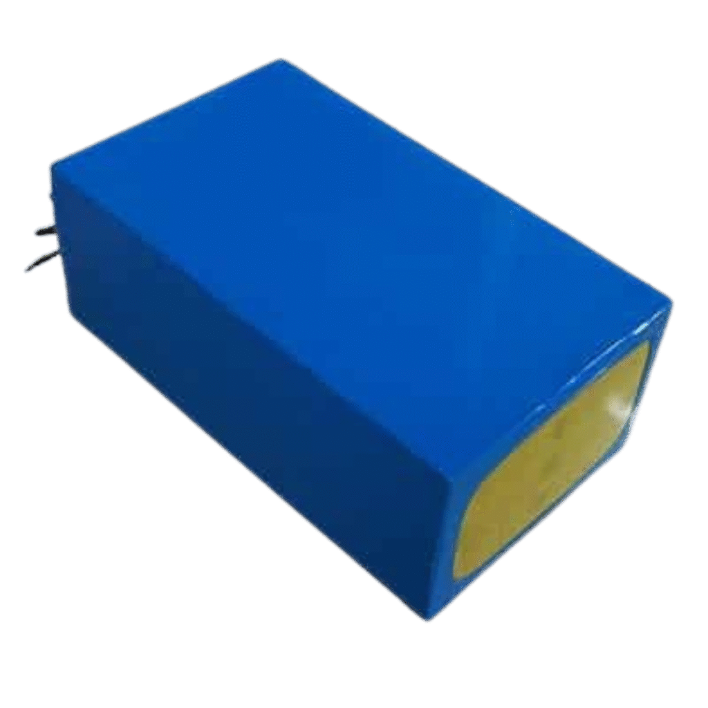
Identify the cart variant and the approved restraint
Start the hold-down inspection from the vehicle model, production variant and available manufacturer instructions. Photograph the battery compartment, existing support surfaces and mounting points before finalizing the hardware list. For fleet vehicles, record previous tray replacements or accessory brackets that may change the available space. Two carts with the same nominal system voltage can have different mechanical interfaces.
Club Car includes battery hold-down condition in its electric-vehicle maintenance guidance and publishes model manuals through its own directory. The Trojan OnePack bundle guide demonstrates how a supplier can assign different mounting bracket part numbers to different vehicle variants. Use those publications as examples of the documentation to request from the vehicle and battery providers. A bracket from one specific kit establishes compatibility only within its documented scope.
Trace where the battery loads go
Ask the technician to identify the supported surfaces and the parts that restrain motion fore and aft, laterally and vertically. Record where pads or brackets bear on the battery case and confirm that these are approved contact areas. Fasteners transmit load into the structure only through the actual assembled interfaces. Loose hardware, damaged tray supports or an incompatible enclosure contact point require disposition under the approved instructions.
One possible conversion replaces a distributed set of batteries with a different enclosure shape. That can leave unused tray slots or shift where the battery rests. Ask for a drawing that shows how the new geometry is supported and which hardware the supplier approves for it. Record the fastener and bracket identifiers in the inspection. If a drawing or approved instruction is missing, keep the mechanical item open for engineering review.
| Check area | Evidence to capture | Question that must be closed |
|---|---|---|
| Vehicle tray | Model variant, tray part or revision, mounting points and condition | Can the specified hardware be fitted to this tray? |
| Battery support | Approved bearing areas and installed case orientation | Are the support and restraint loads applied to the intended surfaces? |
| Hold-down assembly | Bracket and fastener identification, approved installation record | Does the fitted arrangement match the approved vehicle and battery instructions? |
| Terminals and cable route | Photos with protection in place and measured clearances | Can the cover close and the harness move as intended without interference? |
| Fleet release | Signed inspection linked to cart and kit revision | Which carts share this exact installation configuration? |
Measure the installed envelope under the closed cover
Include terminal caps, installed lugs, harness retention and other protrusions in the drawing. Identify the nearest conductive or moving surface and measure using the procedure specified by the vehicle or battery supplier. Seat and lid hardware can have a swept path. A static measurement with the cover removed can miss an obstruction along that path. The required clearance is specific to the documented installation.
In an illustrative layout, a tray-to-closed-cover height of 235 mm and a case height of 210 mm appear to leave 25 mm. If installed terminal protection reaches 230 mm from the same tray datum, the geometric clearance at that location is 5 mm before tolerances and movement are considered. Compare the actual measured envelope with the approved requirement. The worksheet should identify which surfaces and cover position were measured.
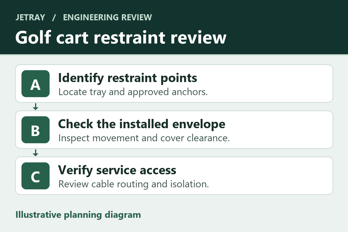
Release the first cart by configuration before ordering the fleet
Jetray's company materials include lead-acid replacement as a product direction. For a golf-cart conversion, use the 36 V product reference and the separate 48 V system inquiry to frame the request for drawings and fitment review. Supply the actual tray measurements and hardware details. Complete mechanical acceptance alongside separate checks for controller, charger and electrical behavior.
For service planning, ask how the authorized technician removes the battery and supports its weight without loading the terminals or harness. Record the lifting access and where the bracket or service panel has to move. Give maintenance staff the approved hardware identification and the vehicle-specific inspection interval. If a later workshop change moves an accessory into the removal path, reopen the fitment record before assuming the earlier service sequence still works.
- Record the chassis, tray, battery enclosure, mounting kit and installed harness revisions for the pilot cart.
- Have the qualified technician complete the documented mechanical checks and retain evidence with terminal protection and the service cover in place.
- Record deviations, responsible reviewers and disposition before placing vehicles into service.
- Use the same release record on matching fleet carts. Reassess any change in tray, accessory, battery case or mounting hardware.
Common hold-down questions at the fleet workshop
When can the existing battery restraint be retained?
When the approved documentation covers the actual battery, tray and restraint together. Confirm contact areas and attachment points before adopting the arrangement across the fleet.
What should the first-cart inspection photo show?
Capture the installed hold-down contacts, tray attachment points, protected terminals and harness retention. Add the cart and kit identifiers to the workshop record so another technician can reproduce the review.
Sources & further reading
- Club Car vehicle maintenance guidelines, electric-vehicle hold-down checks ↗
- Club Car owner and operator manual directory ↗
- Trojan OnePack bundle guide, model-specific mounting bracket entries ↗
This is a mechanical acceptance and procurement guide. Vehicle technicians should follow the approved vehicle and battery documentation. Example dimensions are hypothetical and do not prescribe safe clearances.
Prepared for the golf cart battery projects collection. General engineering guidance does not replace a model-specific datasheet or application validation. Source review: 5 November 2026.